Integrated Automation Design Tool - Automation Studio Educational Edition
Back to Automation Studio Educational Edition page
Main Functions and Features
Circuit creation
Integrated operating environment
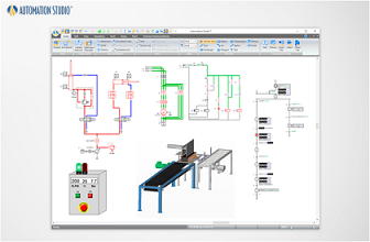
Multiple technologies, such as mechanical, electrical, and electronic, can be mixed and designed in the same circuit editor with a common operation.
Creating a Bill of Materials
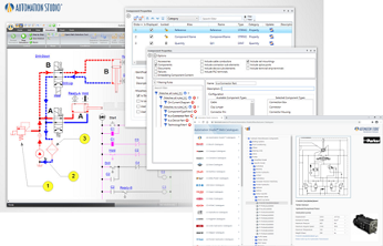
It provides a dynamic bill of materials that can be placed directly on the schematic, exported to create reports, and customized.
Creation of various documents
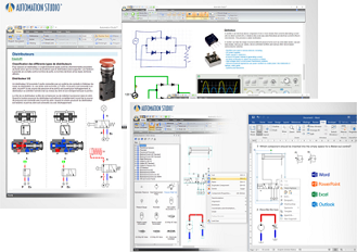
You can insert text and images into the schematic to create a fully documented circuit.
Printing and Exporting
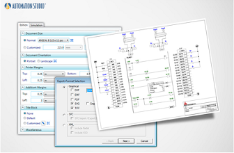
You can print the schematic on any size paper or export the circuit in multiple formats to share with other applications.
Circuit Simulation
Basic Functions
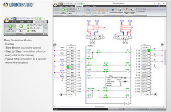
Three simulation modes can be controlled: Standard, Slow Motion, Step-by-Step, Pause, and Full Stop.
Creation of various plot diagrams
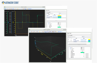
With a simple drag-and-drop operation, the simulated parameters can be plotted and exported to a text file for further analysis.
Equipped with realistic circuit measurement tools
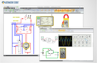
You can have the circuit disconnected during the simulation or have the measurement performed immediately. In addition, measurement tools such as oscilloscopes, multimeters, clamp meters, oil pressure testers, pressure gauges, and thermometers can be used to replicate the actual measurement experience.
Addition and verification of failure scenarios
Create component failures in advance and analyze the behavior of the system in the event of a failure. Students can quickly and easily learn how to solve “hypothetical scenarios” of potential problems.
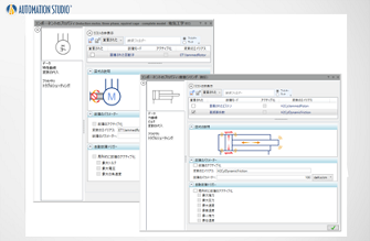
2D-3D visualization
3D Editor
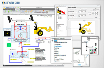
Use the 3D editor to create and import 3D parts in STEP, STL, and IGES. Create 2D or 3D animations linked to circuits to enhance schematics and visually simulate system operating conditions.
Internal structure animation
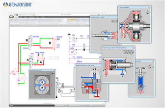
The animated cross-section of a component shows the internal workings of the component. These structural animations can be synchronized with circuit simulations, and can also enhance understanding by visualizing internal operations that are not visible in the real thing.
Control verification of virtual systems
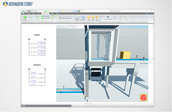
For virtual systems using electrical and PLC libraries and SFC/GRAFCET modules, you can verify system operation in a safe environment by simply following instructions to link sensors, switches, lights, conveyors, etc.
Make a video of the simulation
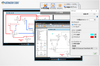
Record and share MP4 format files of all actions (recordable) in project edit or simulation mode, and diagram simulation mode. It makes it easier to visually explain technical aspects of a project.
Custom Libraries
The following libraries are included as standard in Automation Studio 7.1 and later.
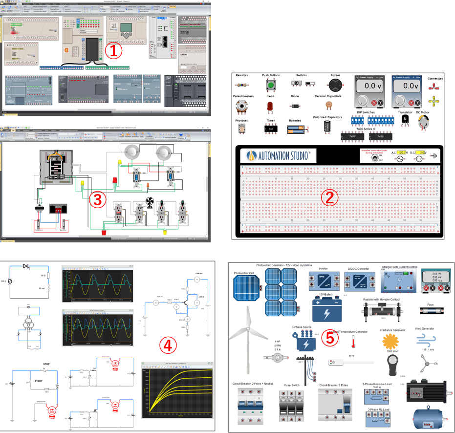
(Click to enlarge)
Overview
-
Describe PLC wiring and ladder logic and run simulations to check inputs and outputs executed by PLCs according to ladder diagrams.
:Allen Bradley, Eaton, Koyo, LS Electric, Mitsubishi, Omron, Siemens, etc.
-
DC components can be connected to breadboard for simulation
:Registers, LEDs, diodes, capacitors, photocells etc
-
Able to create and simulate residential electrical circuits
:Switches, lighting fixtures, fans, testers, breakers, electrical panels etc
-
Semiconductor Devices
Thyristors can be variable or controlled by external circuitry, and transistors can operate in both switching and amplification modes
:Bipolar Junction Transistors (BJTs), Junction Field Effect Transistors (JFETs),
Metal - Oxide - Semiconductor Field Effect Transistors (MOSFETs) Thyristors
-
Renewable energy library provided in illustrated components
:Solar cell, inverter (including 3-phase, breaker, DC/AC motor, MPPT) etc
Support and Services
Manufacturer’s Catalog
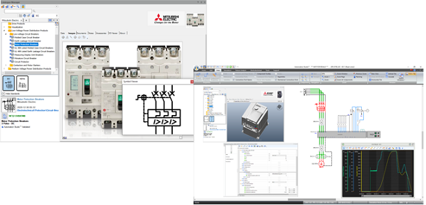
Download PDF specification sheets, 2D symbols compliant with IEC 60617 and NEMA ICS 19-2002, images, technical data, commercial information, 3D representations, simulation models, virtual test benches, and use cases showing component behavior to create and simulate schematics using actual component behavior.